Servo Motor Bearing Failure or Electrical Fault? How to Tell Which One Is Stopping Your Machine
Noise, vibration and heat from a servo motor do not tell you whether the fault is mechanical or electrical — the same symptoms appear on both sides. A worn bearing, a damaged encoder cable, a contaminated connector and a drive fault can all present as a rough-running axis, and ABB notes that electrical bearing damage from shaft currents produces exactly the same early signs: increased noise and vibration, then premature failure.
The reliable way to separate the two is evidence rather than sound: the drive’s own alarm codes, insulation and continuity measurements at the cable and motor, and — when the motor is opened — the damage pattern on the bearing itself. This article sets out that sequence.
What does a failing servo motor bearing actually look like?
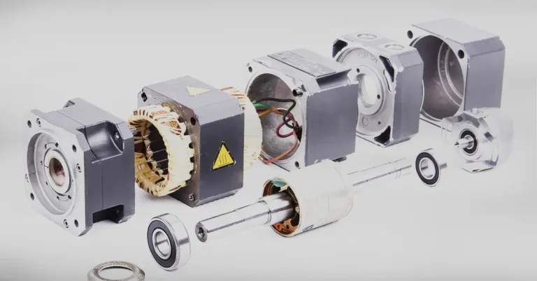
Bearing damage is a physical, inspectable event with a finite set of causes. SKF’s bearing failure guidance groups the problems that are “telegraphed through the bearing” as misalignment, unbalance, looseness and friction, and states the central diagnostic principle plainly: each failure leaves its own imprint on the bearing, and identifying the failure mode is the first step to preventing a recurrence. Damage modes themselves are classified under ISO 15243, the rolling-bearing damage and failure standard.
That principle is what makes mechanical diagnosis possible. A bearing that has failed from inadequate lubrication, from contamination, from misalignment or from an electrical discharge does not look the same when the motor is opened — and the difference decides whether replacing the bearing actually fixes the machine or simply resets the clock.
Source: SKF, “Bearing damage and how to prevent it” and SKF Evolution, “Understanding the ISO 15243 – Bearing damage modes and classifications” (3 March 2021).
Which symptoms point to an electrical fault instead?
Servo drives report electrical faults far more specifically than they report mechanical ones, because the drive is measuring current, position feedback and internal supply rails continuously. In the OEM troubleshooting guide for legacy Sigma-series axis motors, Haas Automation maps symptoms to probable causes as follows:
- Axis drive fault / amplifier short circuit alarms: faulty servo amplifier, faulty power cable, or faulty servo motor.
- Axis servo error too large: faulty encoder cable or connection, faulty encoder — but also a brake that is not disengaging, a damaged ballscrew, or incorrect parameters.
- Axis motor overheat: faulty encoder cable or encoder, a defective control-board axis channel, a defective low-voltage power supply, or an incorrect parameter bit.
- Encoder cable, Z-channel, phase and transition faults: faulty encoder cable or connection, or a faulty encoder on the motor.
Two things stand out in that table. First, several electrical alarms trace to the cable and connector, not the motor — which is why the guide’s first corrective action is always inspection of the connector and cable for looseness, damage, stiffness or contamination. Second, one entry breaks the pattern: “axis servo error too large” can be caused by a mechanical problem — a brake that will not release, or a damaged ballscrew. An electrical alarm is not proof of an electrical cause.
Source: Haas Automation, “Sigma 1 – Axis Servo Motor and Cables – Troubleshooting Guide” (TG0129, Revision B, 05/2026).
How do you separate a bearing fault from an encoder or cable fault?
The OEM procedure in that same guide uses continuity and insulation measurements to split the two, and the logic is worth following in order:
- Power cable. With the cable disconnected from both the amplifier and the motor, measure resistance leg-to-leg and leg-to-ground. The guide’s criterion is that the measurements must show an open connection; end-to-end continuity from one end of the cable to the corresponding leg at the other end confirms the cable conducts where it should.
- Motor windings to ground. Measure the resistance from the motor connector pins A, B and C to chassis ground. The reading must show an open circuit. If it does not, the guide’s conclusion is direct: the servo motor is at fault.
- Encoder path. Reseat both ends of the encoder cable, inspect the connector for damage, and verify the encoder counts per revolution against the machine’s mechanical pitch by jogging the axis and reading the diagnostic counts.
- Contamination check. The guide notes specifically that coolant contamination at the motor connector can generate drive-fault alarms and damage the amplifier — so a connector that looks mechanically fine can still be the electrical cause.
Read that sequence as a filter, not a verdict. Measurements that pass do not prove the bearing is healthy; they remove the electrical paths from suspicion so the mechanical evidence can be read on its own.
Can electrical damage be the real cause of a “mechanical” bearing failure?
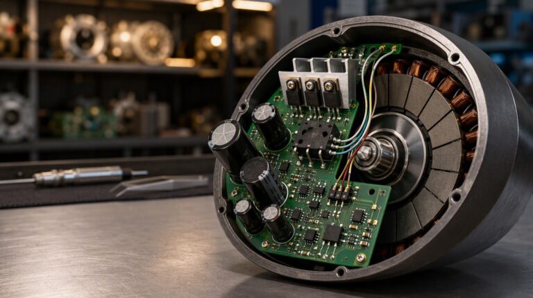
Yes — and this is the failure mode most often missed, because it ends as a mechanical breakdown. ABB describes bearing currents as voltages induced in the motor rotor and shaft discharging to earth through the bearings. The discharge transfers metal between the balls and the races — effectively electric discharge machining (EDM) taking place inside the bearing. The cumulative effect is premature wear, increased noise and vibration, and early failure.
ABB notes this is not a new phenomenon — reports of bearing-current failures date back to the 1930s — and that in variable-speed drive applications, capacitive bearing currents arise from the common-mode voltage of the drive system, with risk tied closely to the specific installation conditions. The company’s Technical Guide No. 5, “Bearing currents in modern AC drive systems”, is the reference document behind that explanation.
The maintenance consequence is uncomfortable but important: if a replacement bearing wears out unusually quickly and the electrical path was never checked, the next bearing may fail the same way. That is an inspection and installation question, not a parts question.
Source: ABB, “Bearing currents and how to beat them” (Jouni Ikaheimo, Technology Manager, ABB Low Voltage Motors) and ABB Technical Guide No. 5, “Bearing currents in modern AC drive systems”.
When is repair the better route than replacement?
For a servo motor, repair is a genuine alternative to replacement — and on legacy hardware it is often the only alternative. Haas’s own service documentation states that the Yaskawa Sigma 1 motors (−02, −04 and −08) used on machines and rotary tables from the mid-1990s to the mid-2000s are no longer in production, and that continued service support depends on refurbishment and repair.
Repair is usually the practical route when the motor is mechanically sound apart from a serviceable item — bearings, encoder, connectors — and when the machine’s control configuration has to stay as built. Replacement becomes the more sensible route when the fault is inside the rotor or stator, when the same failure keeps returning after repair, or when the axis is already being re-engineered.
Which one applies to your unit is decided by the inspection, not by the symptom. Our servo motor and drive repair and recovery service exists for exactly that assessment, including units already down on the line. For Yaskawa SGDM and SGDH generation drives, repair and sourcing support for that series keeps the original architecture running where a migration is not wanted.
Servo motor fault diagnosis — direct answers
How can I tell if a servo motor fault is mechanical or electrical?
Start with what the drive reports: electrical faults appear as specific alarms (drive fault, overcurrent, encoder, phase or overheat), while the OEM troubleshooting sequence separates cable, winding-to-ground and encoder paths with continuity and insulation measurements. What remains after those paths are cleared — noise, vibration, heat and play — points to the mechanical side, confirmed by opening the motor and reading the bearing’s damage pattern against ISO 15243 classifications.
Can a bad bearing cause an electrical alarm?
Indirectly, yes. Haas’s symptom table lists “axis servo error too large” as potentially caused by a brake that is not disengaging or a damaged ballscrew — mechanical conditions that produce an electrical-looking alarm. The alarm identifies where the control loop lost position, not which side of the motor caused it.
Can an electrical fault destroy a bearing?
Yes. ABB describes shaft voltages discharging through the bearings as electric discharge machining (EDM) — metal transfer between balls and races causing premature wear, increased noise and vibration, and early failure. In those cases the bearing damage is real, but the root cause is electrical and lives in the drive installation.
Should I replace the motor or repair it?
Repair is the practical route when the fault is in a serviceable item (bearings, encoder, connectors) and the control configuration should stay as built. Replacement is more sensible when the rotor or stator is damaged, when the same fault returns after repair, or when the axis is already being re-engineered. The decision is confirmed after inspection, per unit.
What do you need from me to assess a servo motor fault?
The motor nameplate and full model number, the drive model, the exact alarm code or fault text, whether the fault appears at standstill, on enable or during motion, and any recent mechanical work on the axis. Photographs of the nameplate and the drive display help.
What should a maintenance team do before replacing a servo motor?
Clear the electrical paths first — cable continuity, winding-to-ground, encoder connection and contamination — and record the alarm history. Only then open the motor and read the bearing. This order matters because it prevents the two most common and most expensive mistakes: replacing a healthy motor because of a damaged cable, and replacing a bearing whose real failure mode is electrical and will simply recur.
Trying to decide on a fault, or on repair versus replacement?
Send the motor and drive model, the exact alarm code, and what the axis was doing when it failed to Ask Star for a repair, replacement or sourcing review. If you would rather look first, browse the shop for verified inventory. For the wider decision logic, see our guide to identifying the right replacement for an obsolete automation part.
Sources: Haas Automation, “Sigma 1 – Axis Servo Motor and Cables – Troubleshooting Guide” (TG0129, Revision B, 05/2026; document last updated 12 May 2026). SKF, “Bearing damage and how to prevent it”; SKF Evolution, “Understanding the ISO 15243 – Bearing damage modes and classifications” (3 March 2021). ABB, “Bearing currents and how to beat them” (Jouni Ikaheimo, ABB Low Voltage Motors) and ABB Technical Guide No. 5, “Bearing currents in modern AC drive systems”. Alarm names, measurement criteria and lifecycle statements above are the cited sources’ own wording; the inspection sequence and repair-versus-replacement guidance is Star Automations’ operational recommendation.