How do you repair the board when there is no circuit diagram?
The sentence comes up in meetings. The drawing is with the parent. The failed module is here. A complete new unit is on lead time. That is not a dead end. Repair without a drawing is normal industrial practice, not guesswork. The board still obeys rules that do not change: input and rectifier, DC link, commutation switches, auxiliary supply, protection, feedback. And a known-good board of the same revision can be laid beside the suspect one. Measurement does the rest. This page is about the mindset and the sequence a long bench follows when there is no drawing to read.
What a drawing would have told you — and what the board still tells you
A schematic names nets. It tells you which pin belongs to which block, so you can probe with confidence. It does not make the board measurable. The board is already measurable.
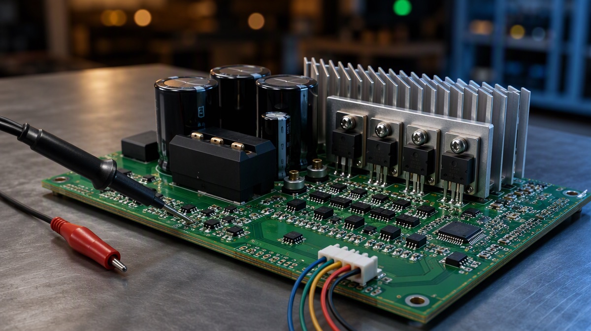
Every EC or BLDC power board carries the same functional blocks, whatever the layout:
- an input and a rectifier
- a DC link
- switches that commutate a magnet rotor
- an auxiliary supply
- protection
- Hall or encoder feedback
An experienced technician does not start at a random IC. He names those blocks on the copper with a meter first — feed points, rails, switching nodes, sense returns. Only then does he unsolder anything.
That is reading the board. It is not copying a design.
The mindset
Five rules, and they are not complicated:
- Do not apply mains to a board that has not been screened power-off. A shorted switch takes the next part with it.
- Compare before you conclude. One failed board without a twin is slower work. A known-good board of the same revision is the missing page of the manual.
- Replace by specification. Not by colour, and not by the cheapest part that fits the pads.
- The board is not finished when it lights. It is finished when the rotor commutates cleanly and the release points pass.
- Stop. Some boards are beyond repair. Saying BER is part of the job.
The sequence on the bench
The order is what separates a result from a mess. The order is the method.
- Incoming. Photograph the unit, note the nameplate, map the connectors, and write the fault as received.
- Power-off comparison. In-circuit signatures and rail-to-rail checks against a known-good board. On dense, multi-layer and fine-pitch layouts this is where the job is decided — you are looking for the stage that behaves out of character, not for a burnt mark.
- Power stage measurements. ESR on the electrolytics, junction behaviour on the semiconductors, and a hard look at the drivers sitting between them.
- Find the failed stage. Supply, switch, driver, sense or Hall. Name it before touching it.
- Rework to published assembly practice. Remove, prepare the land, fit the equivalent, inspect. IPC-7711/7721, current revision D, is the published procedure family for component rework and assembly repair. Fine-pitch and area-array packages need a controlled heat profile and a supported board — not a quick touch with an iron.
- Source from the datasheet window. Voltage, ripple current, ESR, package, temperature. If no equivalent can be proven against those limits, stop there.
- Alignment after the board is live. Hall or commutation sequence has to match rotor position. A live board with the wrong position reference still trips.
- Functional test on the assembled module, not on the bare board. Control input at 0–10 V or the interface the unit actually uses, then current, speed or Hall activity.
- Record it. What failed, what was fitted, what was measured. The customer relationship, and the scrap-or-reuse call, stay with the brand owner.
Why “we already tried” often fails
The stop-points repeat, and they are worth naming without blame:
- Powering a shorted DC link
- Changing every capacitor without measuring ESR
- Fitting a lookalike FET
- Skipping alignment after a board swap
- Shipping on “it spun once”
This is why a complete-module swap feels safer. It is also why a documented bench is the other option.
What this is not
We are not an authorised cell for any manufacturer.
This is not a promise that every layout yields. Some boards are beyond repair.
And it is not IT or laptop work.
Repairing an EC board without a drawing — direct answers
How can a workshop work if the manufacturer will not release a circuit diagram?
The board still has measurable blocks: input, DC link, commutation switches, auxiliary supply, protection and feedback. A known-good board of the same revision is compared power-off and in-circuit. The drawing is useful. It is not the only way to find a failed stage.
What does an experienced electronics man do first?
He does not apply mains. He maps the blocks, compares signatures or voltages to a good board, and only then unsolders the part that is out of tolerance. Replacing parts at random is how boards get worse.
How do you choose a replacement component without the original part list?
From the failed part’s markings and from the datasheet limits the circuit requires — voltage, current, ESR, package, temperature. A part that only “fits the pads” is not an equivalent. If no equivalent can be shown, the board is not rebuilt.
When is the repair finished?
When the assembled module passes a functional test: control input, current, speed or Hall activity, and commutation without abnormal vibration or trip. A board that only lights on the bench is not released.
What should we send if we have already tried and failed?
The module as it now is, a note of what was already changed, and a known-good board of the same hardware revision if one exists. Nameplate photographs help. Some units will still be beyond repair; that has to be said before any rebuild.
Send the module, and the good board if you have one
Send the failed module as it stands, including whatever was already changed. If a working board of the same revision is on your shelf, send that too — it turns comparison into measurement instead of guesswork. Nameplate photographs help.
Start with the requirement form and the Priority Technical Review. The rotation and feedback side of this work shares a bench with our servo motor repair work, so alignment questions do not leave the building.